Operation Guide | Operation Instructions for A-max Butt Welder
- Share
- publisher
- WELPING
- Issue Time
- Sep 24,2026
Summary
The differences between the A-max series butt welding machines and the A series welding machines.
Operation Instructions for A-max Butt Welder
The differences between the A-max series butt welding machines and the A series welding machines.
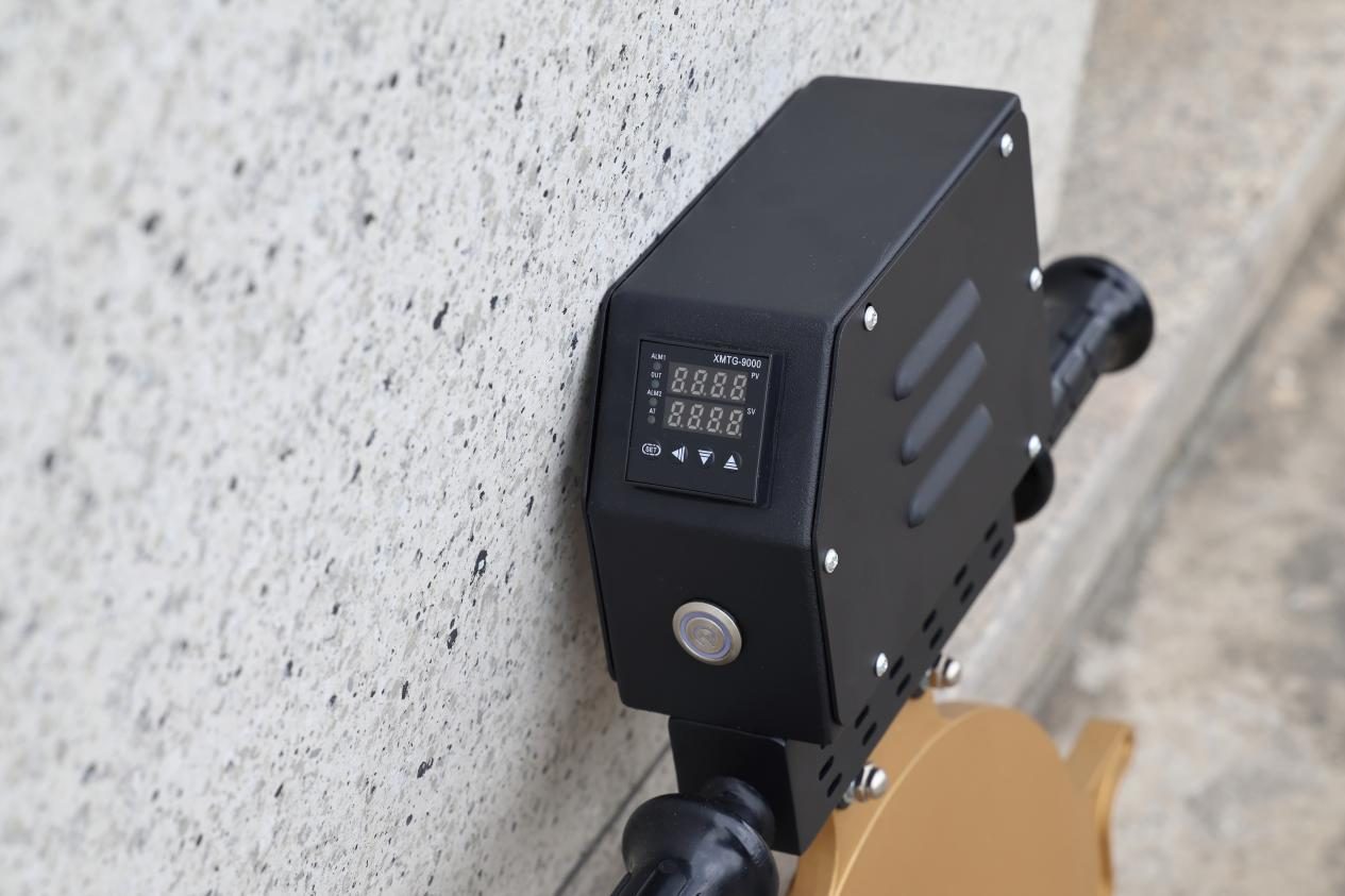
1. The heating plate of the A-max butt welding machine adopts independent control, which uses a separate temperature control method to enable temperature adjustment.
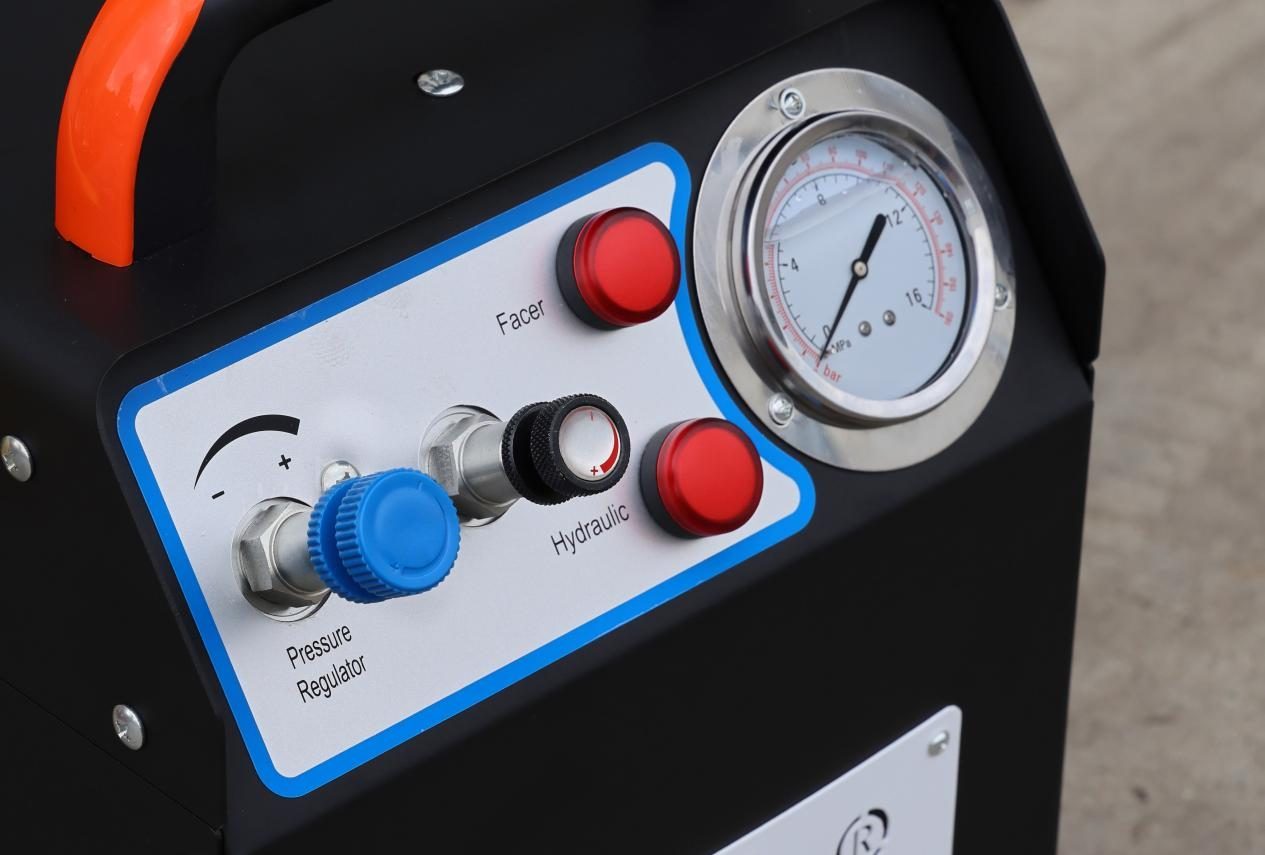
2. The hydraulic station of the A-max butt welding machine breaks through the original pressure control mode, making the operation simpler and more intuitive. The blue one is the pressure regulating valve (with limit), and the black one is the control valve (with limit).
The red ones are the milling cutter indicator light and the hydraulic station indicator light, with a pressure gauge next to them.
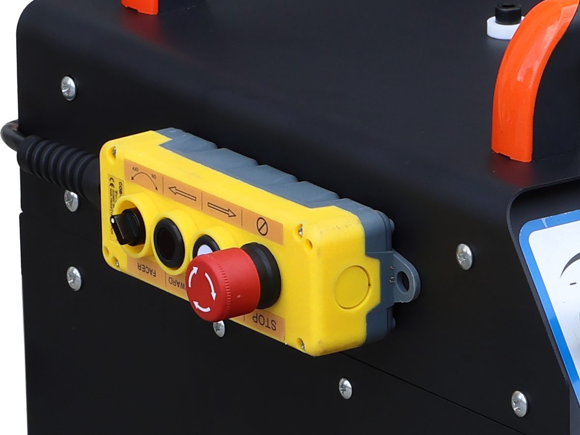
3. A proximity remote controller for A-max butt welding machine, which is equipped with a milling cutter switch, a forward/backward control for the rack, and an emergency stop button.
Briefly introducing the differences between the machines, we then proceeded to the actual operation.
1. Replace the breather cap, insert the oil pipe, and connect all types of power supplies.
2. Place the pipes on the rack and secure them completely.
3.Test the drag pressure and calculate the welding pressure. (When testing the drag pressure, the control valve must be opened to the maximum. Then slowly increase the pressure regulating valve until the oil cylinder starts to move. Record the drag pressure value Pt.)
4.
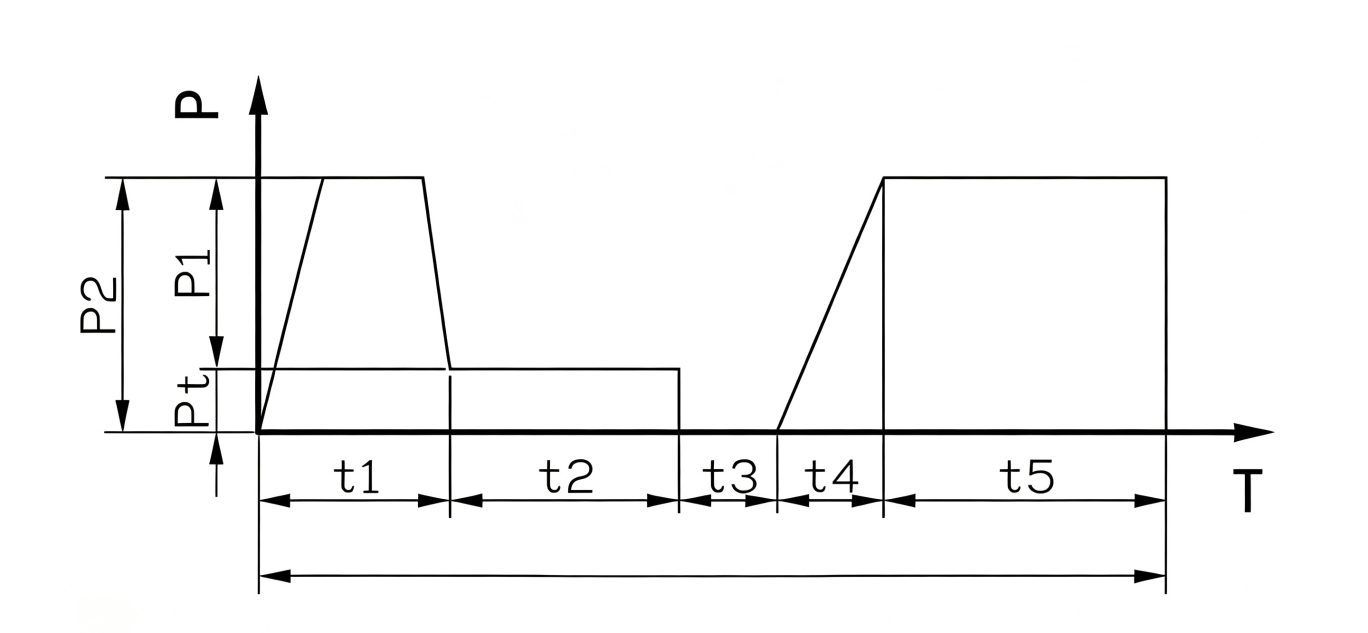
Case: For the PE315 SDR11 pipe, the welding pressure (calculated via the formula) P1 is 28 bar, and the drag pressure is 2 bar.
Turn the control valve (black) to the maximum position ➡️ Hold the forward button on the remote control, meanwhile rotate the pressure regulating valve (blue) to 30 bar and secure it with the stopper. ➡️ Turn the control valve (turn it slowly towards the decreasing direction to let the pressure drop to 2 bar) ➡️ Open the frame, insert the milling cutter and start cutting. ➡️ Open the frame, remove the milling cutter, check for misalignment and make adjustments. If the result is not satisfactory, re-cutting is allowed. ➡️ Turn the control valve (turn it towards the increasing direction as far as possible to the maximum) ➡️ Insert the heating plate ➡️ Press the pipes with the total pressure (p2 = 30 bar) and start flanging.➡️t1 Flange to the appropriate height, turn the control valve (turn it downward until pt = 2 bar) ➡️t2 Use drag pressure to absorb heat ➡️ Turn the control valve to the maximum (or set a custom limit, the pressure gauge still reads 2 bar at this point) ➡️t3 Remove the hot plate ➡️t4 Align the pipes, apply pressure from 0 to p2 (p2 = 30 bar) ➡️t5 Cool down (at p2 = 30 bar)